
.png)
“Every percentage count” — That is the reason for developing the new nozzle profile. Brunvoll’s hydrodynamics took all the nozzle profiles we know, broke them down into parts, and studied them closely to understand what parameters that should be tweaked in order to achieve the behavior and performance that we wanted.
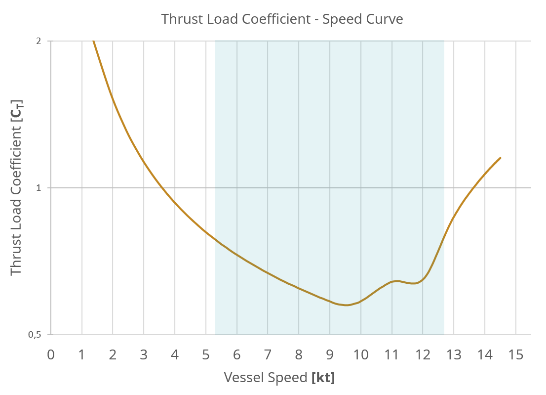
The following graph shows the thrust load coefficient versus speed for a twin-screw anchor handling vessel. These vessels are typically equipped with propulsion systems designed primarily to meet bollard pull requirements, using large propellers with correspondingly large nozzles.
A common characteristic of such configurations is a significant drop in efficiency at higher transit speeds—i.e., in the cyan-shaded area where the thrust load coefficient is low. This is the area where the DL1 nozzle is designed to deliver a marked improvement in performance compared to conventional designs.
This case examines a pelagic vessel with a single-screw shaftline propulsion system, a type of vessel that requires good performance in both bollard pull and transit conditions.
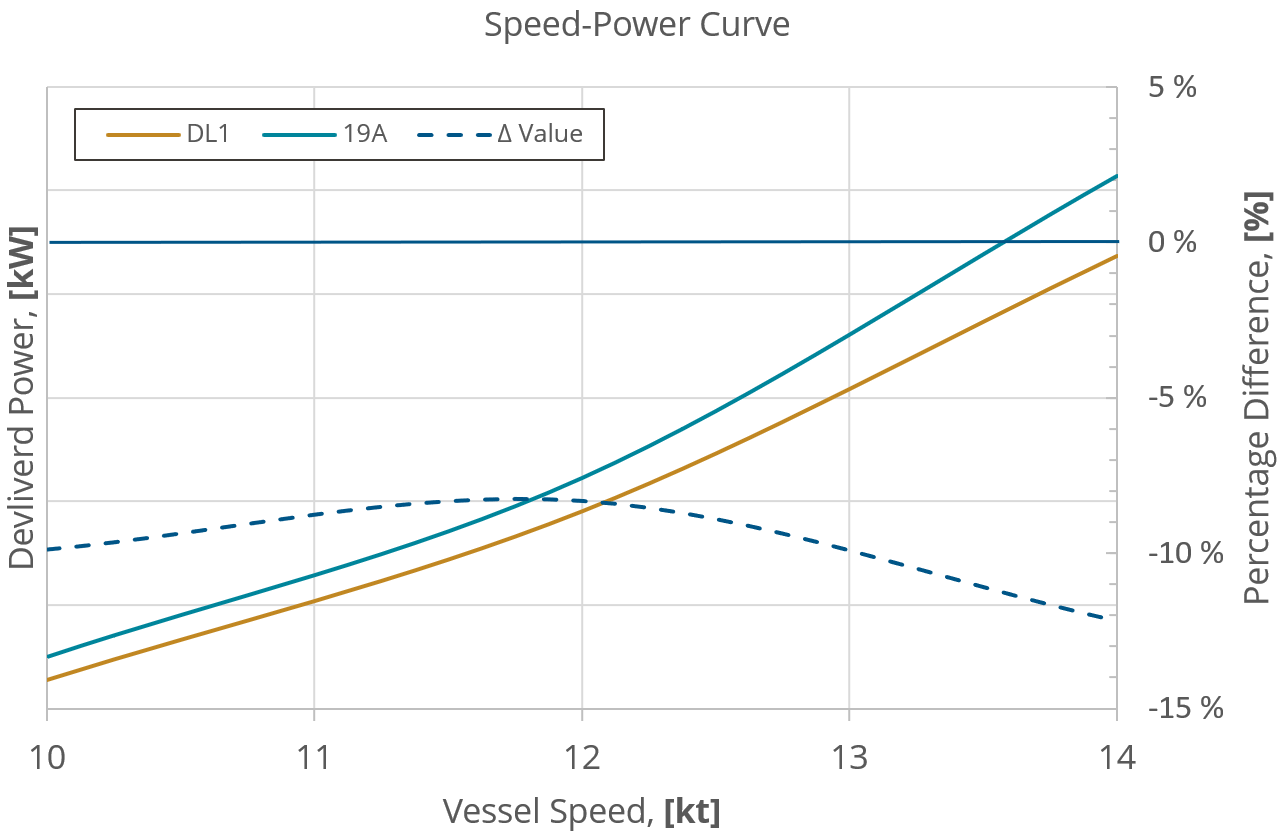
The following speed–power curve compares the propeller efficiency of the DL1 and the 19A nozzle under transit conditions — that is, with a lightly loaded propeller. The right-hand axis shows the percentage difference in efficiency between the two nozzles. For example, at a speed of 13 knots, the DL1 requires 10% less energy input than the 19A to maintain the same speed.
Another important aspect of a nozzle is its astern performance, an area where some designs often fall short. In open water reverse conditions, the DL1 nozzle delivers 28% higher thrust compared to the 19A nozzle.
This case covers a Service Operation Vessel(SOV) / Offshore Supply Vessel(PSV) equipped with a conventional propulsion system comprising two azimuth thrusters. These vessels demand similar performance traits as fishing vessels but also have strict requirements for station keeping capabilities.
The 19A nozzle performs exceptionally well under bollard pull conditions and expecting the DL1 to match that performance may seem like a stretch, given the compromises made to improve transit efficiency. However, Brunvoll’s hydrodynamics team has developed a design that delivers 99.6% of the thrust produced by the 19A — a remarkable result considering the improved overall efficiency.
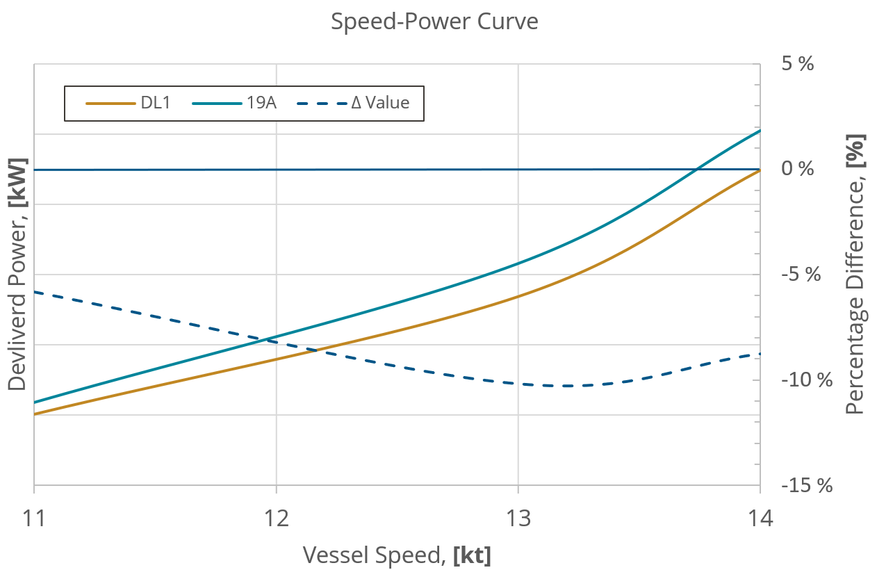
The speed-power curve for the offshore supply vessel compares the delivered power of the two different nozzle profiles as a function of vessel speed. For instance, at 13 knots, the DL1 nozzle requires 10.3% less energy to maintain the same speed as the 19A.
A nozzle also influences the cavitation characteristics of the propeller, which is another key performance indicator used in evaluating the different designs iterations that led to the DL1-nozzle. The following illustration shows the cavitation margin for the two nozzle designs, using the same propeller geometry.
Some cavitation is expected with conventional propeller and nozzle designs. The key, however, is to avoid cavitation that may cause damage to the vessel and its equipment, such as erosion, reduced performance, or increased maintenance needs — as well as cavitation that can negatively affect crew health and comfort, by contributing to elevated levels of noise and vibration.
The illustration highlights the cavitation margin on the suction side of the propeller — i.e. the side facing the inflow. While both nozzle designs show signs of cavitation near the propeller tips, the DL1 demonstrates a greater margin elsewhere, indicating improved hydrodynamic performance.
.png)
.png)


